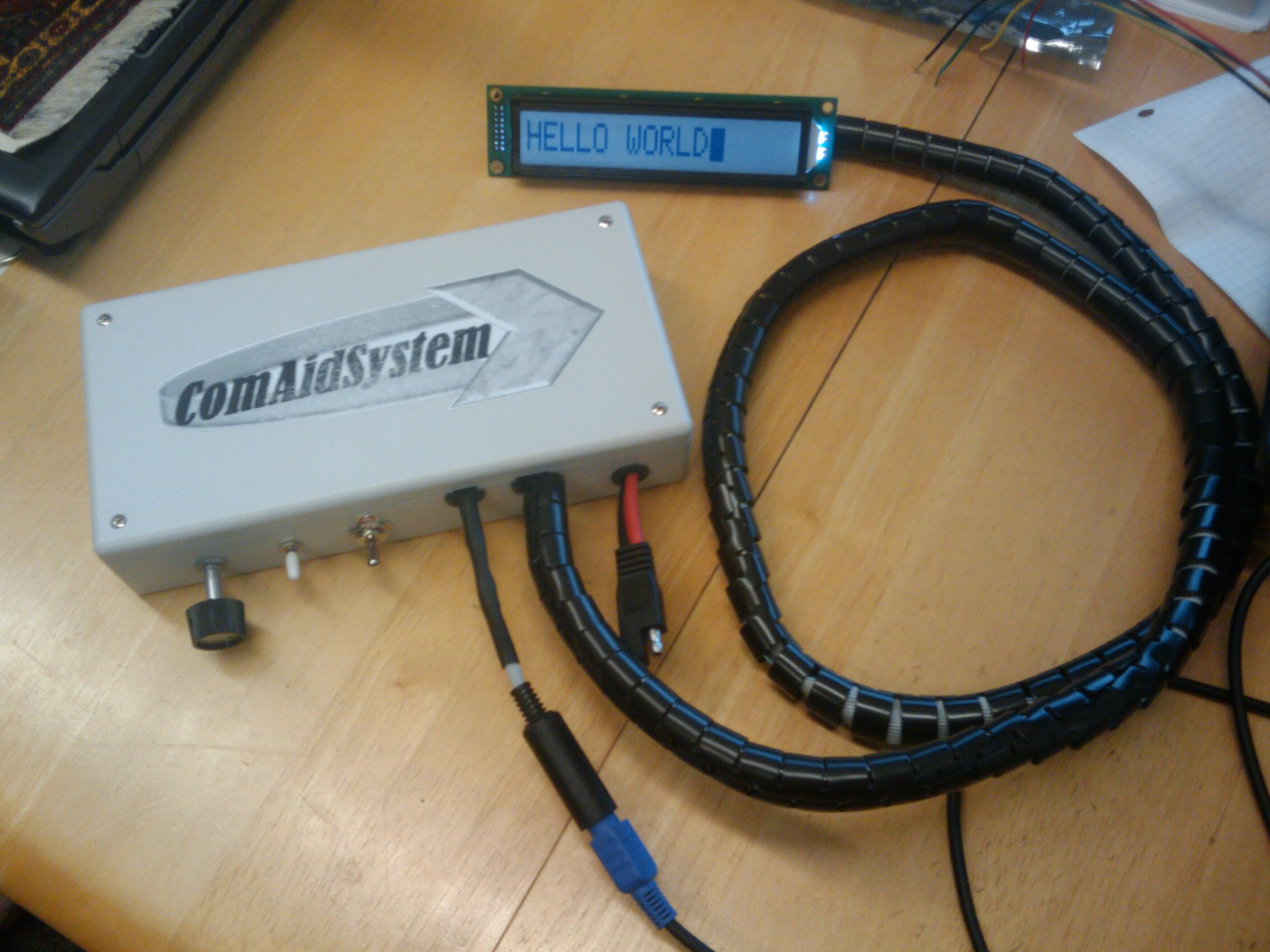
ComAidSystem (Communication Aid System)
an embedded system written in C
May 2010
By Joseph Paul Cohen, Timmy Mbaya, Brendan Davis

This device was designed to aid people with on-road communication with a deaf driver. It is designed to aid a deaf person in having a conversation when reading lips is not appropriate. These situations include driving a car or boat. This device allows a user to type messages using a keyboard while another user reads the message from a screen. We support a standard PS/2 keyboard.

main screen main screen

This device has 2 power sources. One is a 9-volt battery that is located inside the main box. The other is a Regulated Switching Power DC/DC Converter. The power is controlled via a DPDT (Double Pole Double Throw) switch. The concept of this switch is to not to shut the unit off but to select the power source. To set the unit off you would turn it to external power and unplug the external power. Most cars turn off their Cigarette lighter outlets when the car is turned off to save energy. This device will work seamless in those situations as it will power off when the car is off. This device has a voltage regulator to turn both the 9-volt and 6-volt inputs into the 5-volts that run the entire device. Analysis of the device using a hand held voltage meter revealed a current draw of 40ma without significant fluctuation during AVR interrupts, LCD character printing, or keyboard presses. In two cases the power can differ. If the back-light is turned off then the current draw is -20ma. When the Number Lock LED is illuminated the current draw is +20ma. The keyboard provided with this device does not have a Number Lock LED.


results screen results screen

At the heart of comaidsystem is an array of scancode structs with 2 attributes, a char variable and a function pointer (Please, refer to description of keyboard.h for details). We opted for this model with upgradability and easy maintenance in mind. We beleive that this model optimizes upgradability becuase the function pointers for the various keys can easily be changed to point to new functions depending on what result we want a key press to produce. For instance, the system can easily be turned from a communication aid device to a game console or a motor control just by adjusting the function pointers and the hardware without having to rewrite whole sections of core code. This array of scancode structs (scancodes[0xf1]) is directly indexable with scan-code values, however it has a gigantic memory footprint [only large for this environment!]. Thus our choice involved a trade-off between footprint and upgradability/maintenance/performance. We thought upgradability/ maintenance/performance was a better trade-off because without the scancode structures the code might have involved numerous if statements and switch blocks which are actually long assembly instructions resulting in relatively big footprint, not to mention code complexity and cumbersome upgradability. Also we thought future development for various dedicated real-time embedded systems might benefit from O(1) indexing, instead of an O(n) loop through a smaller array.


AVR Memory Usage
----------------
Device: atmega168p
Program: 3608 bytes (22.0% Full)
(.text + .data + .bootloader)
Data: 793 bytes (77.4% Full)
(.data + .bss + .noinit)

Above is some memory analysis of the AVR chip loaded with production software.

admin screen admin screen

comaidsytem.c: Contains main(), calls to API (for initializations...), a "forever loop", and "pure-AVR" functions for enabling interrupts, setting up the keyboard, and handling interrupts. Its primary goal is to initialize the system in order to receive interrupts from the keyboard whenever a bit is sent, and then decode the received scancode (a series of bytes from the keyboard when a key is pressed, held, and/or released) direct indexing into the scancode struct array to atomically determine what operation to execute, either display on LCD or specific commands (by calling the API's process_scancode(unsigned char) function). The content of the file is described below:


int main()
{
	//initializes bitcount to 11 (1 start, 1 parity, 8 data, 1 stop
	bitcount = NUM_BITS;
	
	//initializes system global variables
	init_sysvarStates();
	
	//Enable pin change interrupts from the keyboard clock
	enable_pcint(KB_PCINT);

	//Initialize scancode tables
	initTables();
	
	//Sets up the keyboard after BAT test
	keyboard_setup();
	
	//sets AVR global interrupt flag
	sei(); 
	
	// enable: nlcd_init does not by default
	nlcd_init(); 
	nlcd_enable_scrolling(); 
	
	//clears the LCD screen
	deletefn(NO_USE_CHAR);
	
	//forever loop . Everything will happen within the 
	//interrupt handler whenever interrupts are set off by the keyboard
	while(1)
	;
	
	return 0;
}

ISR(PCINT1_vect) PCINT8-14 :Interrupt Service Routine for pin change interrupts from Receiving scancodes from the keyboard: After the initialization that allows for the pin to be used as an interrupt when a rising edge is received, the scancode will set off the ISR for the PCINT that its signal is connected to.
1. Negative edges are what indicate that a bit has just been received. We are ignoring the start bit, the parity bit, and the stop bits. We read whether or not the edge is negative or positive. The ISR is set off regardless of whether it is a rising or falling edge, so it was theoretically possible to simply have a variable alternate between two states to indicate whether we are on the rising or falling edge. When testing with this approach, however, we found that the variable switch was unreliable,while directly reading from the PCINT port [pin] was very reliable. Using an edge switching variable would have been more appropriate if we had used AVR's ATmega168p designated external interrupt pins, INT0 and INT1. These pins would have been better suited for use with a switching edge variable as they can be set to trigger interrupts either at the rising, falling, high or low edges, However they are in use by the programmer and LCD in our configuration. Therefore we had to use the PCINT's (precisely PCINT11), Atmega168p pin change interrupts, which can be set as external interrupts by setting their data direction registers to input. However, the downside with them is that they toggle between high and low (whenever the keyboard sends signals) and set off interrupts whenever this happens. The bitcount variable counts down from 11bits (start+stop+parity+8data)
2. The received data bits are buffered in a local char variable and once have received 11 bits altogether, we decode the isolated data bits by passing the local char variable holding them to the API's function process_scancode(char_data) as shown in the code below:

ISR(PCINT1_vect){
	static unsigned char char_data = 0;
	
	//If negative edge, ignore start, parity and stop bits and read bit
	if ((PINC & (1 << PINC3)) == 0 ) {
	
		//we only take the 8 data bits
		if (bitcount < NUM_BITS && bitcount > 2) {
			char_data = (char_data >> 1);
			if (PINC & 0x04)
			char_data = (char_data | 0x80);
		}
		
		//If we received a byte...
		if (--bitcount == 0) {
			bitcount = NUM_BITS;
			
			//Decode and process received scancode
			process_scancode(char_data);
		}
	}
}

enable_pcint(int pcintnum), AVR's ATmega168p provides INT0 and INT1 as main sources for external interrupts. These pins would have been better to use as they can be set to trigger interrupts either at the rising, falling, high or low edges, but they are used by the programmer and LCD in our configuration. Therefore we had to use the PCINT's (precisely PCINT11), Atmega168p pin change interrupts, which can be set as external interrupts by setting their data direction registers to input. However, the downside with them is that they interrupt on any toggle between high and low and set off interrupts whenever this happens. Here is how we configured PCINT11 as an external interrupt source:

void enable_pcint(int pcintnum){

	//We use PCINT11 but we could have used other PCINT's
	if ((pcintnum >= 8) && (pcintnum <= 14)) {
	
		//Enables pin change interrupts from PCINT8-14
		PCICR |= 0x2; 
		//Unmasks pin change interrupt from PCINT11 only
		PCMSK1 |= 0x8; 
		//Sets PINC3 as input for data
		DDRC &= ~(1 << DDC3); 
		//Sets pull-up on PINC3
		PORTC |= (1 << PORTC3); 
		//Completes Tri-state (Hi-Z) DDxn:0 PORTxn:1 PUD:1 (MCUCR)
		MCUCR |= (1 << PUD); 
		//Sets PINC2 as input for data
		DDRC &= ~(1 << DDC2); 
		//Sets pull-up on PINC2
		PORTC |= (1 << PORTC2); 
		//Completes Tri-state (Hi-Z) DDxn:0 PORTxn:1 PUD:1 (MCUCR)
		MCUCR |= (1 << PUD); 
	}
}
to be finished later...

More documents can be found here Manuals